Table of Contents
Introduction
This is the second in the 2-part series “Bass Shakers for your Sim Rig.” In the first part which you can find at the previous link we covered the software side, now it’s time put in a little elbow grease and nail down the hardware aspect. Below you will find a list of the components you will need.
Required components
You will need:
- 2 x 25w Bass Shakers
- 2 x Puck Bass Shakers
- Assorted self tapping screws
- USB surround sound card 5.1 or 7.1
- 2x 5v 2 channel amplifier boards
- 14-gauge speaker wire
- 2 x Screw terminal to headphone jack adapters
Assembly
Front: Bottom of wheel stand/pedals.
First take the 2x 25w bass shakers they should look something like this.

Or if you are lucky enough to track down a pair of the old-style low power bass shakers which I personally prefer they will look something like this.
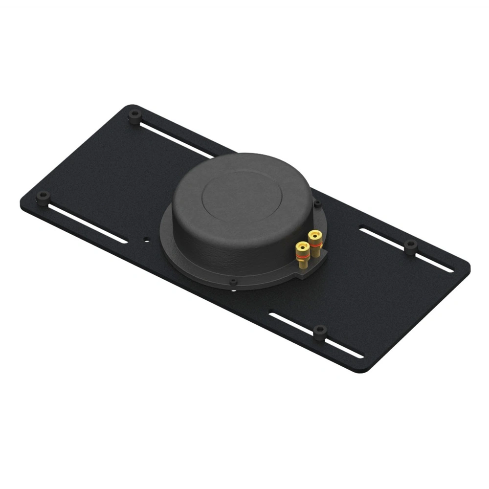
Regardless of which style you wind up with you’re going to put one on the left underside of either your pedals or the footrest of your wheel stand. It appears that the new style has adhesive pads you can try to stick them with. If you have the older style, you’ll have to hunt down some appropriately sized nuts, bolts, and washers. Regardless make sure that they are firmly attached to whatever surface you have chosen to mate them too.
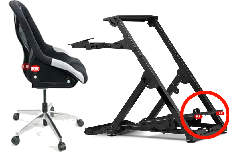
Run a good 3′ of 14-gauge speaker wire from the terminals on either bass shaker, try to run them under the frame so there is no chance for you to hook your foot or anything else on them in the future.
Rear: Underside of your racing seat or gaming chair
Next, you’ll want to take the two “Puck” style bass shakers which will look like the following picture.
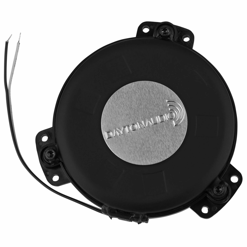
These two will go on either side of your seat, if you have a sim rig where the seat and the wheel stand are one piece go ahead and run the speaker wire as you did with the first pair. If you are using an office chair, gaming chair, or any chair that is not physically attached to the rest of your rig you are going to want to find a double female RJ11 phone cord coupler/phone line extension like below.
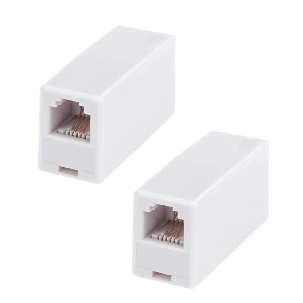
Hot glue or super glue the coupler to the bottom of your chair somewhere underneath the seat on the same side where you will have the amps and power supply. You’re also going to need a phone cord you can sacrifice for the cause. You’ll want to take the phone cord and cut it in half, stripping the 4 different color wires you find inside back a half inch to an inch or so.
Now with the speaker wire the same as you did for the front make some leads from the 2 bass shakers. A foot or two long should be plenty, so long as they reach the cut phone cord with some slack left over. Now take some heat shrink tubing and connect the leads from the bass shakers to the stripped phone cord. — Make sure to remember which leads go to which color wire. —
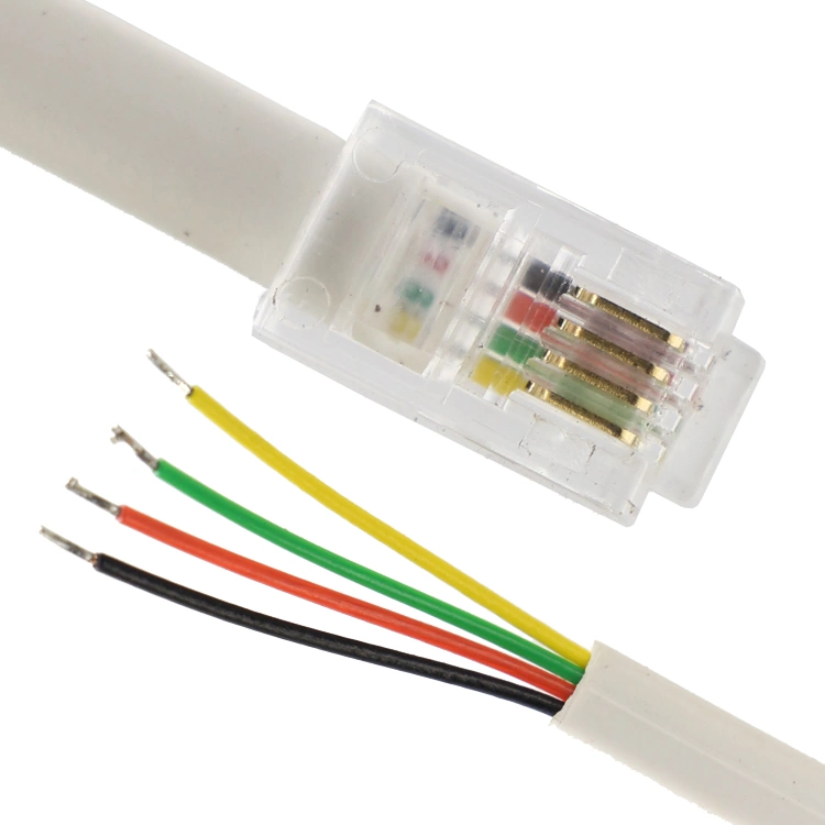
Now that you have your bass shakers attached to the phone cord — also make sure the little tabs are still on the ends of the phone cord you use. — Now plug that phone cord into the end of the coupler that is harder to get at, staple or otherwise secure any extra lengths of wire and you are done with the chair.
Amplifiers
Take the two amplifier boards and secure them to a board either with screws, or hot glue can work as well but screws are preferred. Strip and tin 4 lengths of the 14-gauge speaker wire long enough to reach from where you plan to mount the amps to your bass shakers. The amp boards will look something like the following.
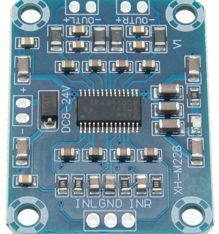
You’ll solder the leads into the top of this picture labeled “outr” and “outl.” If you don’t want to try your hand at soldering for a few more dollars you can buy basically the same board, accept it comes prepopulated with screw terminals.
You will run the leads from one of the amplifier boards to the other half of the phone cord you cut up earlier, then plug that into the coupler attached to the underside of your chair and your rear channels are done. For the front channels just go ahead and run them straight to the bass shaker on the underside or pedals.
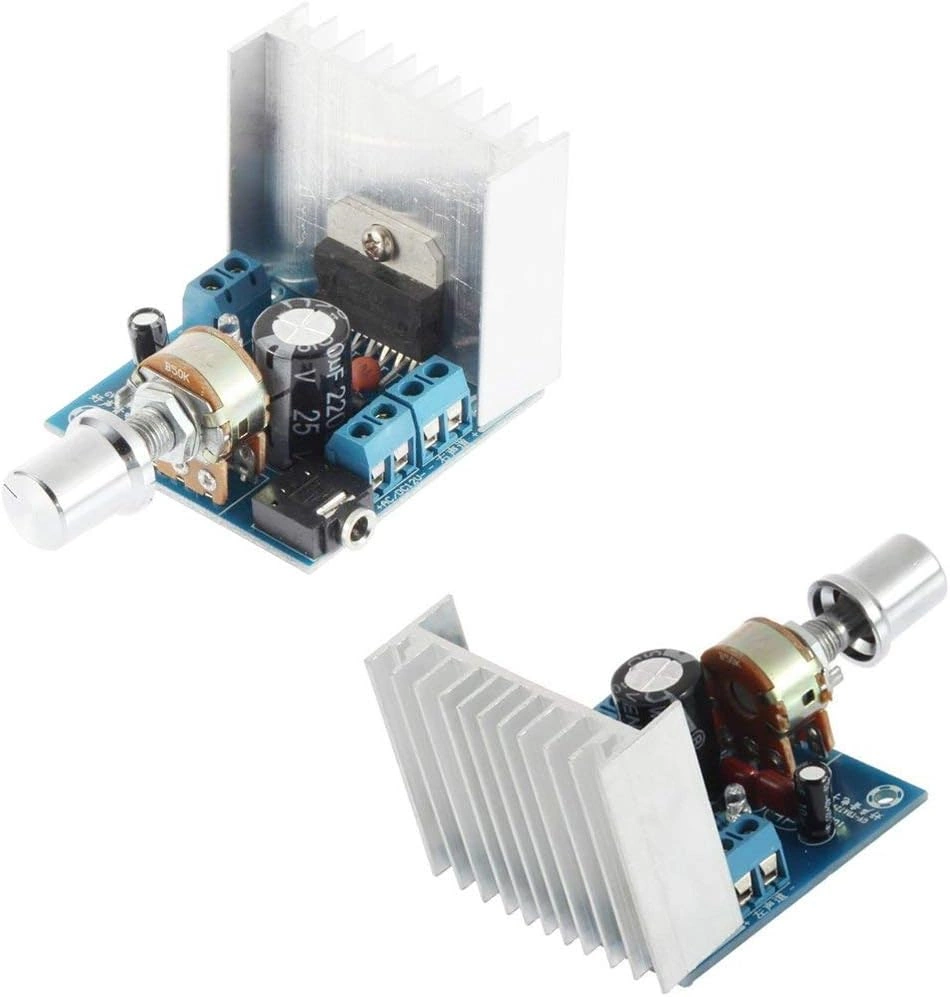
Next figure out how you are going to power the amps. You can cut up a wall wort, or use a dedicated power supply if you like? Regardless run lines for power and ground for both amplifiers.
Sound card
One thing to be aware of when you pick out a surround sound card is to be sure you get one that is real 5.1 or 7.1 and not virtual. You can tell the difference because the real one will have far more places for headphone jack connections.
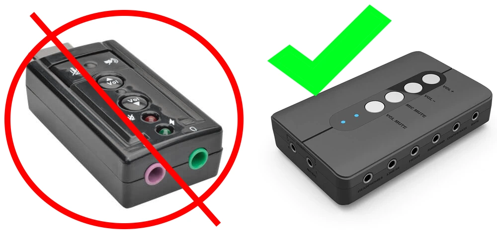
Finally plug in and get the drivers loaded for the usb soundcard. Once the soundcard is installed figure out where you plan to mount it, then measure out 3 lengths of the speaker wire that will reach from the amps to the soundcard with some extra length add on. One of the lengths you will have to split the pair of wires into 2 separate single wire, so you are left with 2 pair of three wire sets when done.
One end will either be soldered or attached to the amplifier terminals — Left, Ground, Right — on the other end you’re going to need a pair of screw terminal to headphone jack connectors. They will connect — Left, Right, Ground — both ends share a common ground for each channel.
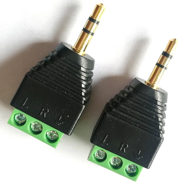
Make sure to get the ones with 3 terminals and not 4. Once you’ve got that setup plug them into which ever channels of the usb soundcard you are using for your outputs in SimHub and you are set. Go ahead and fire up your favorite racing sim load up a profile in SimHub or start to experiment and make your own. Regardless you’ll feel the purr of the engine, a jolt when you make contact, and the rumble of rumble strips when you hit the track!
Conclusion
While this is quite an undertaking, in my opinion it is well worth the effort. If done right this can give you another way to tell what the car is doing on track and if you are pushing it too hard or maybe not close enough to edge.
Related
Are your Fanatec pedals giving you trouble, jittering or constantly losing calibration? Click through that link, and upgrade those troublesome potentiometers for some never wear out hall effect sensors.
Maybe you’ve thought about how handy a button box could be for setting up pitstops or making in car adjustments? Here is a virtual button box using your smartphone.
Need something a little more advanced than just a button box? How about a full fidelity dashboard for your virtual racecar with Sim Dashboard?

[…] *This post got so long that I have decided to break it into a 2 parter. Part 1 is here and concentrates on software, part 2 found here covers setting up the bass shaker hardware. […]