Table of Contents
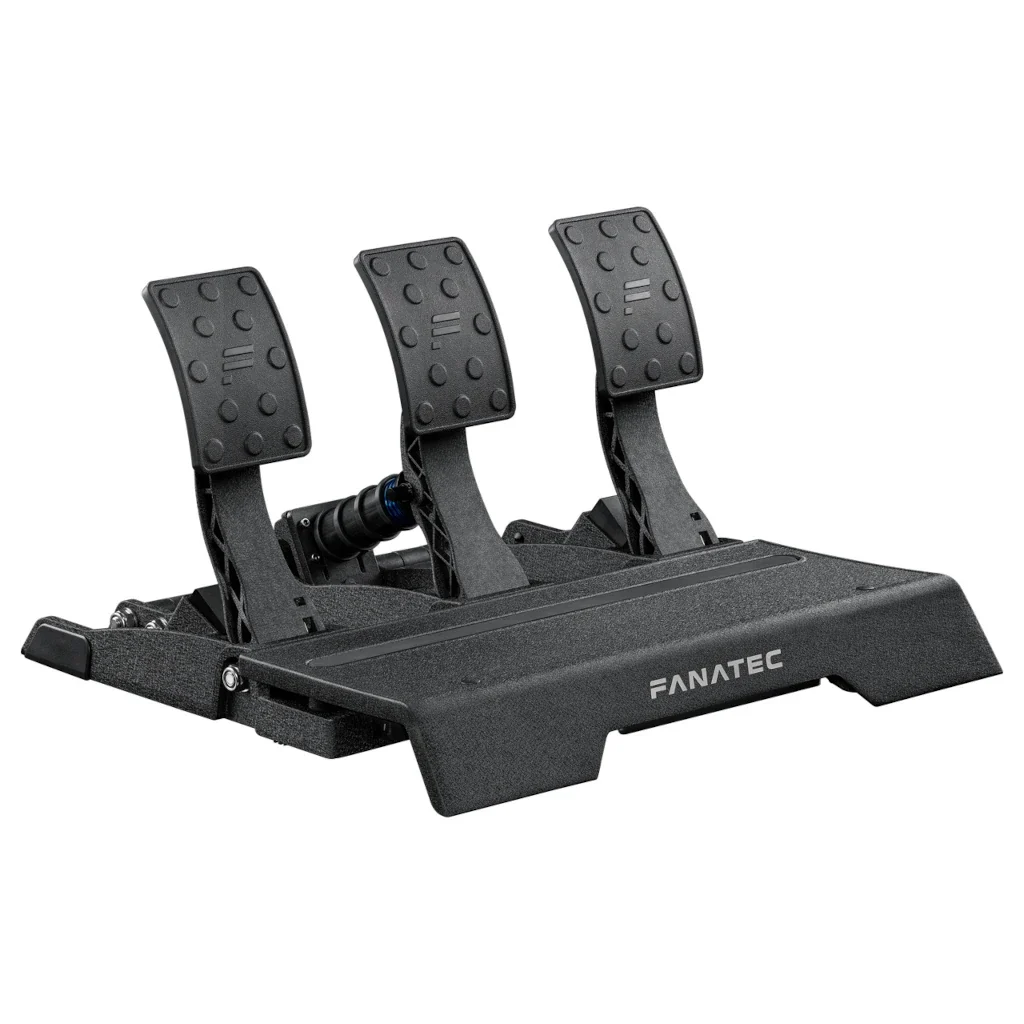
I successfully performed this Fanatec Pedals Upgrade from potentiometers to hall sensors myself more than a year ago. I own the Fanatec CSL Elite V2 Pedal set, now this should work with most Fanatec Pedals, but I can’t 100% guarantee that. I race daily, I’ve put in thousands of laps in iRacing and thousands of miles in Dirt Rally 2.0 since then. Performing this mod was one of the best things I have done, I
have had zero issues with my gas pedal ever since. No calibration updates, not the slightest jitter, just buttery smooth input every single time.
Acknowledgment
Credit for this awesome Fanatec Pedals Upgrade mod goes u/Archangell22, and u/hellothereshinycoin over on Reddit and also the Fanatec forums. I stitched this article together by combining these two Reddit posts and this thread on *Fanatec’s forum *which may have been removed because I can no longer find it, so all props really belong to them. I decided to combine everything here because trying to coherently follow instructions on one Reddit thread is no picnic — I can’t be the only one that gets a headache from any more than an hour on Reddit am I? —
Fanatec Pedals Upgrade: Replacing the potentiometer in my CSL Elite gas pedal with hall sensor.
This is how I did it. If you also choose to do this, be aware you’re probably voiding the warranty and while I didn’t break anything doing this, — I’d peg difficulty at about 3.5 out 10. — Anyway, you’ve been warned I can’t be responsible if you do manage to break something! There’s a small list of things you will need to purchase that you probably won’t have laying around the house, unless you’re a bigger geek than I am, and if so, we should really hang out some time! These are the magnets and sensors that I used and can say for sure work.
Fanatec Pedals Upgrade: Parts List
- HALL SENSOR:
- Allegro Microsystems A1325LUA-T
- MAGNETS:
- 1x NEB38P752512 – 0.75in x 0.25in x 0.125in N38 block magnet
- 2x NEB38P502512 – 0.50in x 0.25in x 0.125in N38 block magnet
- 1x N35P375250HT – 0.375in diameter, 0.25in height N35 disc magnet
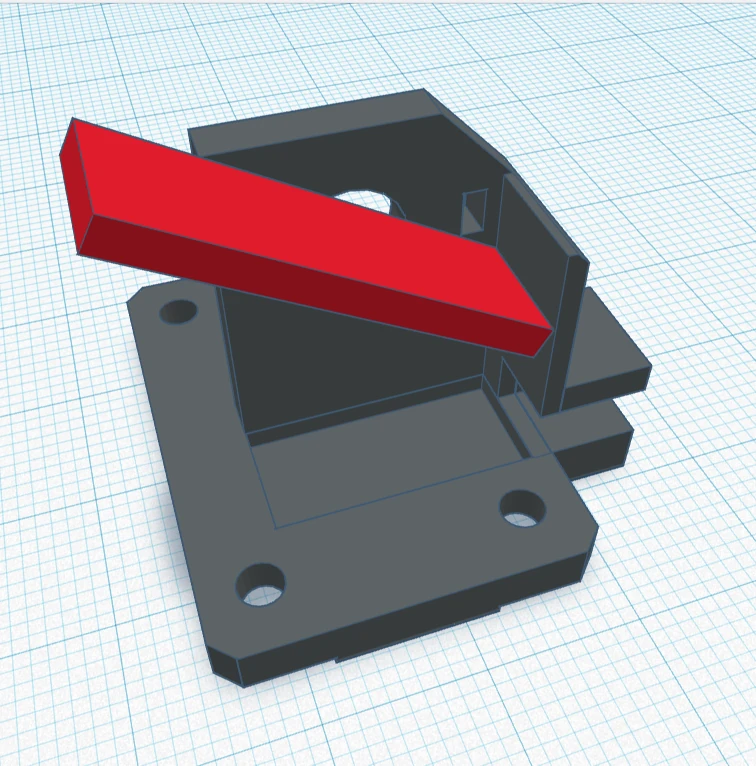
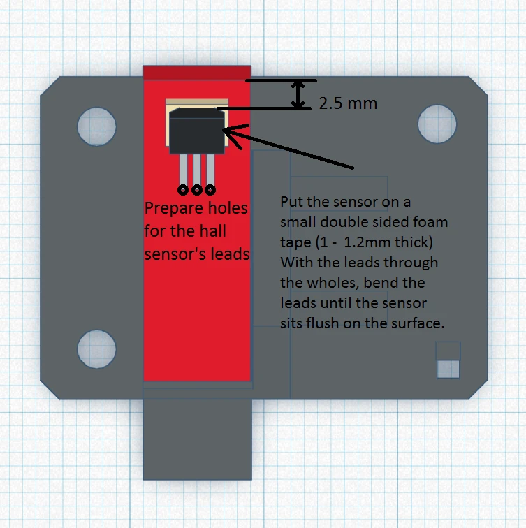
- *3D PRINTED Hall sensor housing:
— Using the provided Ebay links (I’ll get them generated and placed very soon I swear!!) You’ll have a few spares just in case, and you help out the site in the process! —
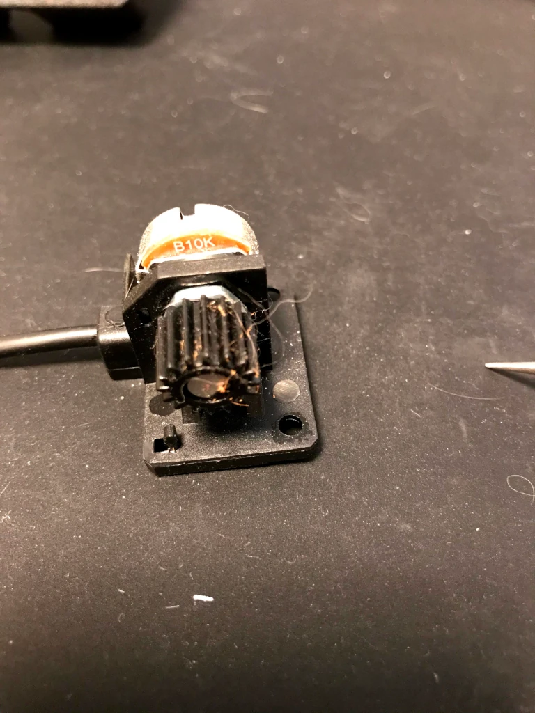
*Do yourself a favor and don’t try to MacGyver something together with popsicle sticks and super glue like I did the first time. It was nothing but a mess and non-stop aggravation.
STL file: https://drive.google.com/file/d/1Q9Ruk0A1jtoFUf8mav7U_ryUqV0-pR8a/view?usp=sharing
You can have this printed anywhere you choose; I got mine printed by a kid I found on Craigslist. He ran off 3 of them for me and it only set me back $20. No matter where you get yours from, you’ll probably have to drill out the 1mm holes for the sensor wires yourself as the 3D print process melts holes that small.
Fanatec Pedals Upgrade: The Process
- Starting from the pedal is removed from pedal set and module underneath.
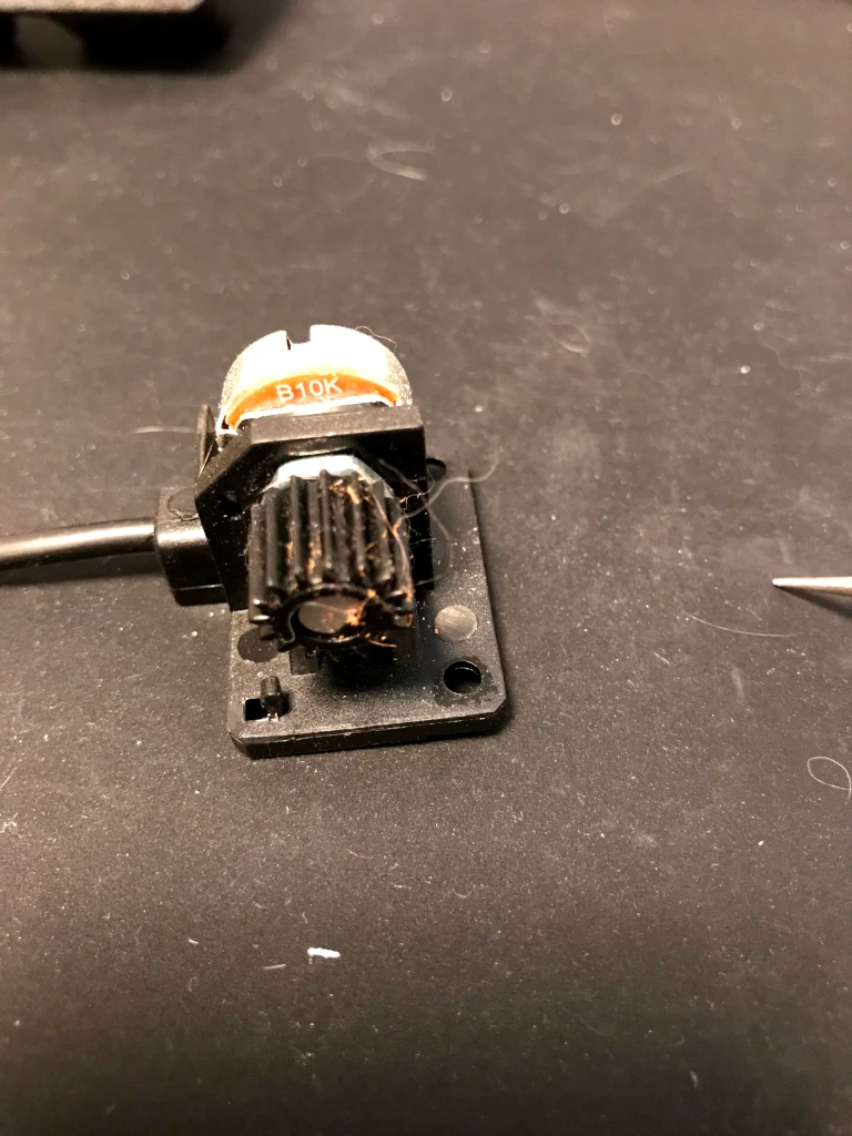
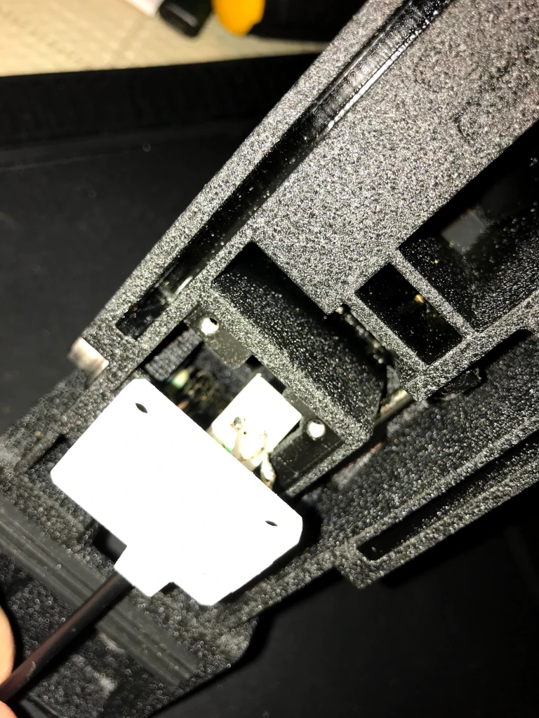
- Remove the existing potentiometer mount from the pedal by removing the 3 screws underneath the pedal and then pushing on it gently from the top to push the housing out the bottom.
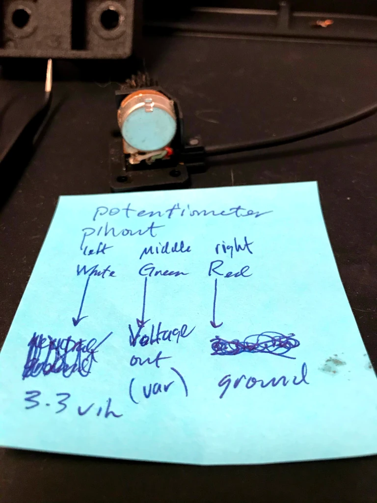
- Note your pinouts on the potentiometer are, if you are looking at the connection
- left: Voltage in
- middle: Voltage out (variable)
- right: ground.

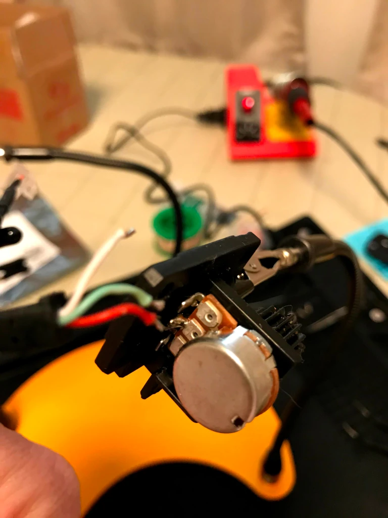
- Desolder the 3 small wire connections to the potentiometer, note what color is what as it might differ from my pictures.
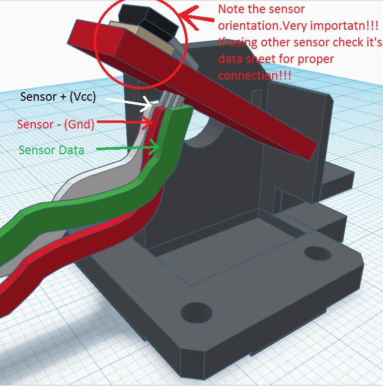
- Place hall sensor in the 3D printed housing, carefully bending the wires where appropriate and putting them through the 3x 1mm holes.
- Solder the RJ12 connections that you removed from the potentiometer
to the hall sensor, matching pinouts (hall sensor is logo up left to
right:- left: Voltage in
- middle: ground
- right: Voltage out (variable).

- Check connectivity in your solders using a multimeter between RJ12
connector and hall sensor make sure each wire has connectivity, and
nothing is cross connecting. - Once connectivity is verified, superglue the hall sensor down to the
mount in the obvious place with a very minimal amount of glue, hold it a
bit longer than you think you might have to, so it fully sets,
superglue the RJ12 cable to the housing in the area it’s intended to go
through, to keep it from moving. - Put the hall sensor housing, now assembled, where the potentiometer
housing was and screw it in using same 3 screws you removed earlier. - Magnets time: two sets of magnets to worry about, one is “in” the
pedal and the other is behind the pedal where there is a notch/cutout
near the spring, that area rotates almost directly over where the hall
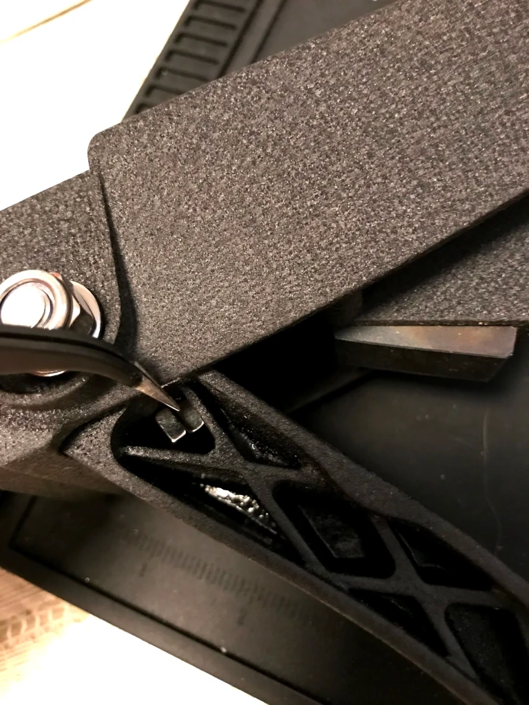
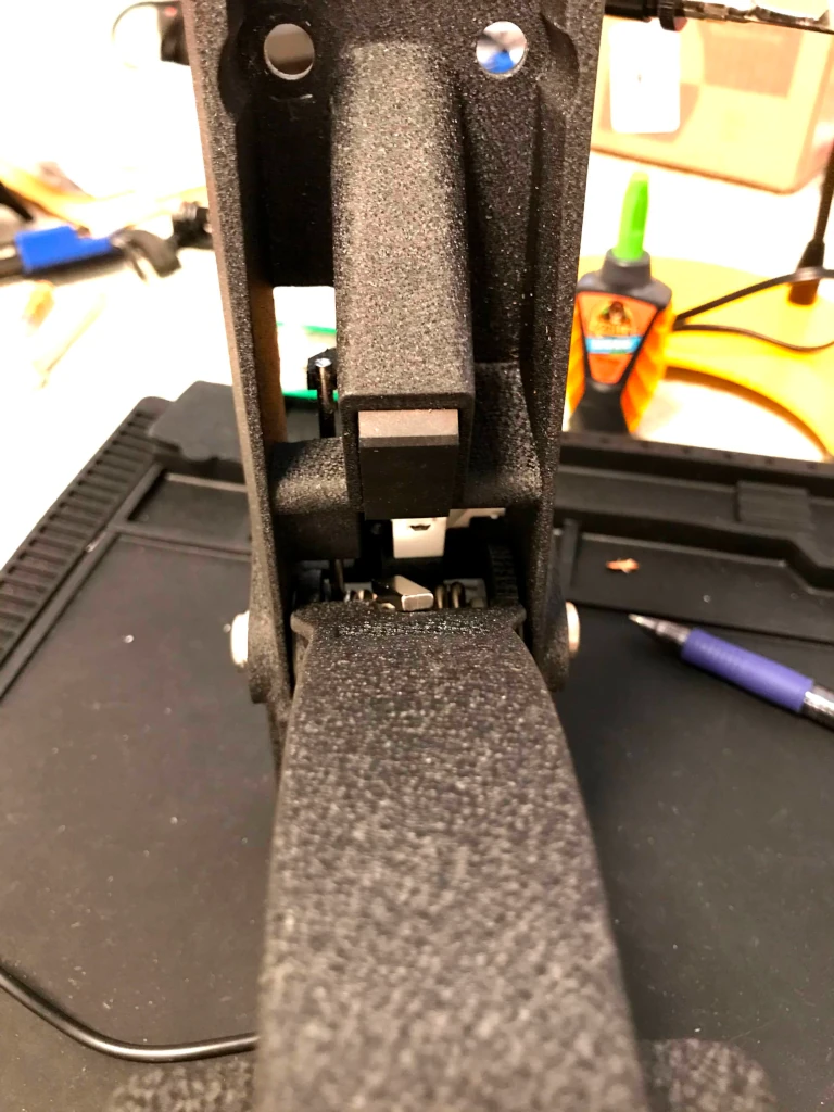
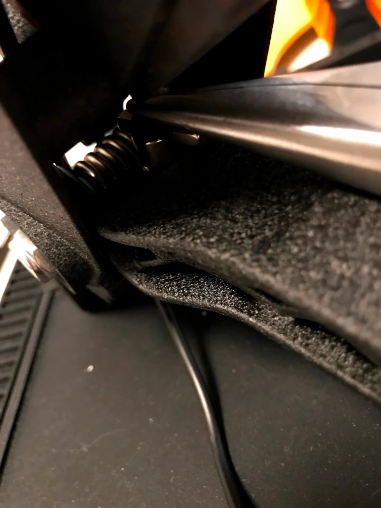
sensor is now located. - *Put one of the half inch block magnets in the pedal honeycombed
area where I am pointing with tweezers, don’t worry about orientation of
this first magnet, it has room to move in there and will orient itself
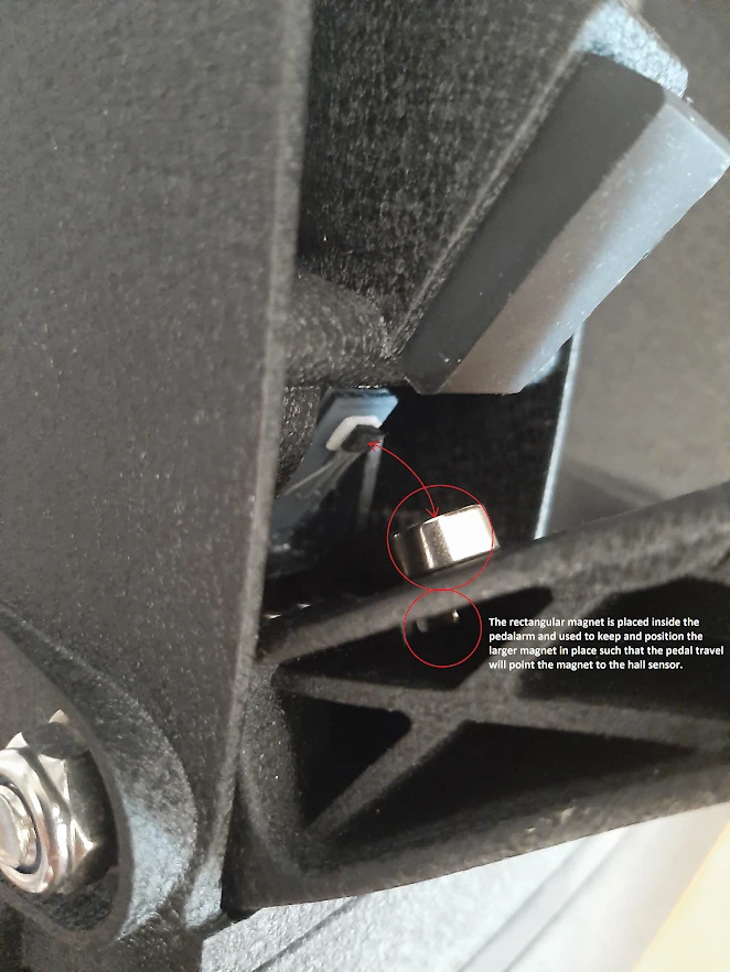
with the next step. - This step you have a 50/50 chance of orienting the wrong magnet pole
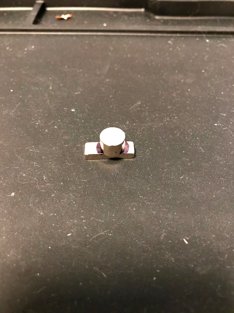
upwards, good luck!) connect the disc magnet and the 3/4-inch block
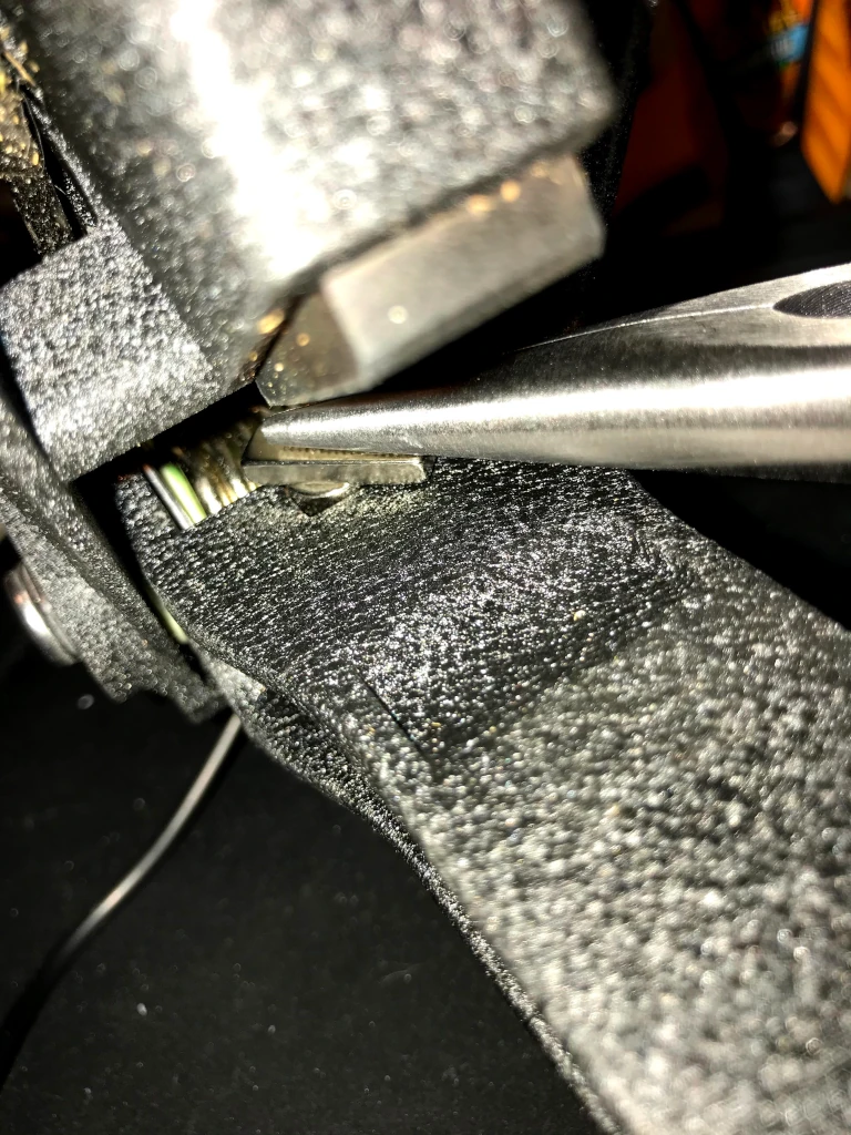
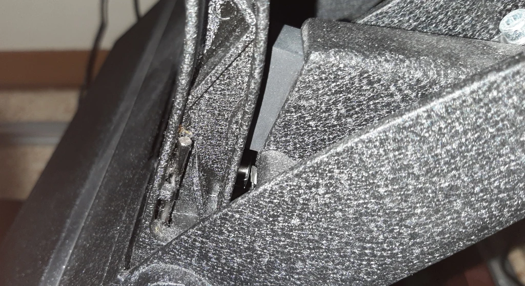
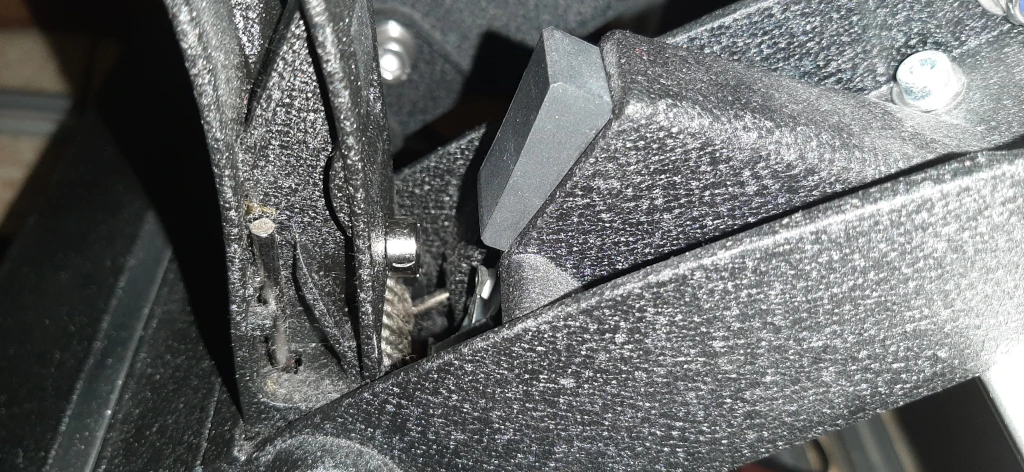
magnet as shown in my pics, like a fat Tetris piece. - Using needle nose pliers, orient the two now connected magnets into
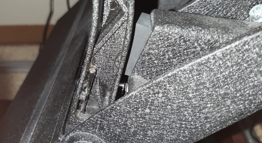
the slot near the spring behind the pedal as shown in my pics with the
block magnet facing the hall sensor, when you get close the disc magnet
will pull itself into the slot, and orient the magnet inside the pedal
correctly and those two keep each other in place now. - Now we see if you guessed right, go plug the pedal in and test it
see if you see signal, if you do NOT see a signal you need to go flip
the two magnets on the back of the pedals, they need to still connect
the same way like a fat Tetris piece, just so the other magnet pole is
facing the hall sensor. - So now you’re either testing again and seeing signal or you skipped
step 13 because it gave you signal initially, we have to now orient the
block magnet so that when you press the pedal you get signal right after
pressing the pedal, and max out signal near the end of the pedal range
(short or long, either is ok but close is good) - The way the magnet is sitting in that slot on the back of the pedal
and the shapes of them means you can just spin the block magnet by very
small amounts like you are setting a clock, until it’s mostly lengthwise
along the pedal but spun a little bit towards the hall sensor. You’ll
see when you play with it, if it looks like it does in my pictures. You
aren’t dialing in the final orientation just making sure you can get a
full linear range of input at this point. Once you see that you can,
disconnect pedal for final steps. - Once you see full linear movement in the pedal range (by
orienting/spinning the block magnet little by little until it’s just
right) we’re just locking in the orientation/suction power of these
magnets, so they don’t move. - Add one more 1/2-inch block magnet to inside the pedal, the
honeycomb area where the one 1/2-inch magnet already is, put this one
underneath the other one so they stick together (but now they won’t be
able to rotate in there like the one could before) - Extract the two magnets (fat Tetris piece) from the back of the
pedal (do not separate them yet) (leave the two 1/2-inch magnets in the
honeycomb area in the pedal, they will not fall out on their own) - Mark with a sharpie how these magnets are currently stuck together,
they must stay oriented this way from here on out; superglue them
together in that orientation, very carefully as you only get one shot.
Practice a few times before putting the glue down, so you get the
incoming angle right, you let go in time not to get your fingers stuck
in superglue etc. If you are a little off that’s ok, you’ll just have to
fiddle with the final orientation a little but once they snap together,
they are stuck. The reason for doing this is so that the block magnet
no longer rotates around the disc magnet. Disc magnet can still rotate
where it sits, but it has a lot more friction compared to the block
magnet/disc magnet connection area. - Let the superglue set for longer than you think it needs, give it 5 minutes.
- Once fully set, put the 2 magnets, now superglued together into fat Tetris for eternity, back in the back of the pedal
- Do your final orientation/calibration so your pedal has a full
linear input range, and the magnets will stick there until/unless you do
something severely drastic to your pedals (then just “spin the clock”
again to re-orient for the linear reading from the sensor)
Enjoy!
Fanatec Pedals Upgrade: Additional High-Res Images
If anything was unclear or a little garbled, it’s probably because I’ve had to change hosts and restoring my posts from the first website… Let’s just say it wasn’t a smooth process. So again, if you want a better view of something here is a link to one of the original authors google drive folder. He has over 40 high-res pictures documenting every step of the process: Google Drive.
Related
Interested in another hall sensor upgrade for a flight stick this time? To stick with the sim racing genre, we can help you setup your triple monitors, plus make it easy to switch between 1 and 3 screens with the click of a link. How about a full fidelity dashboard that supports just about every racing sim there is? Or if all you’re after is a virtual button box we have a FOSS option you have got to see.
[…] out another detailed write up of a hall sensor conversion for sim racing pedals this […]
[…] Fanatec Pedals Upgrade: Hall Sensors Mod Gives Awesome Results! […]
[…] your Fanatec Pedals been jittery? It’s simple to upgrade to hall effect sensors and kiss that problem […]
[…] your Fanatec pedals giving you trouble, jittering or constantly losing calibration? Click through that link, and upgrade those troublesome potentiometers for some never wear out hall […]
[…] to race sim like a pro, from the digital full fidelity dashboard to the triple monitor setup, and upgrading jittery potentiometers for smooth hall sensors in your pedals. We’ve got you […]