Table of Contents
How to Fix a Burned-Out Graphics Card: Introduction
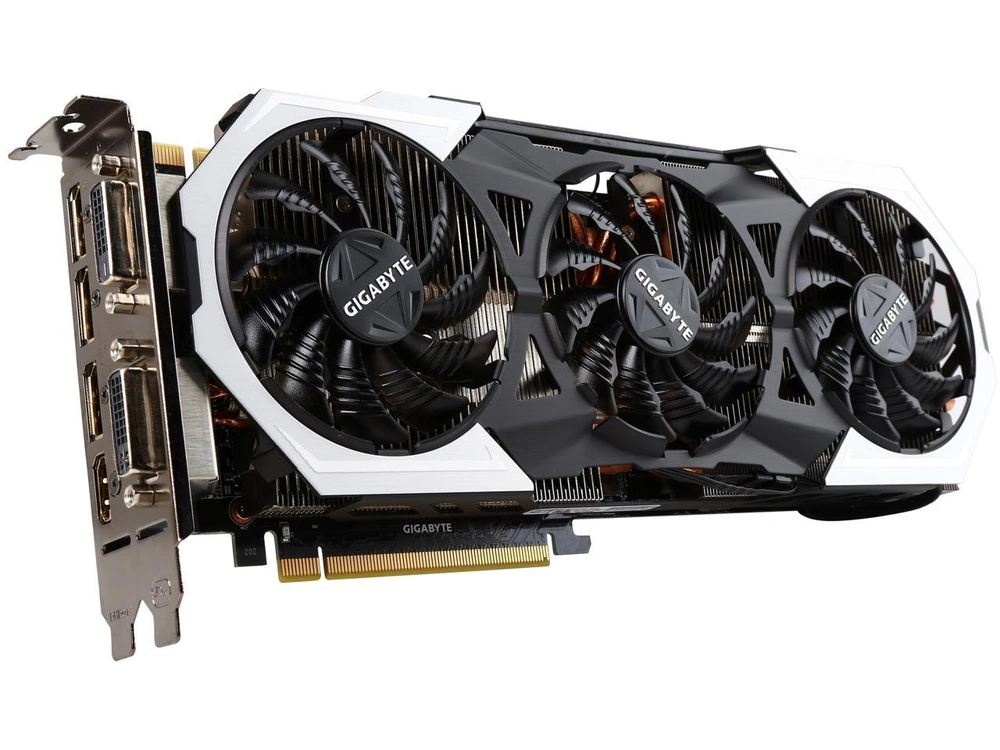
If you missed part 1 of this series on “Fix a burned-out Graphics Card” where we troubleshoot and diagnose what failed on our graphics card the post is at the preceding link. A short recap. It was a buck converter. Done…
Fix a Burned-Out Graphics Card: The Parts Arrive
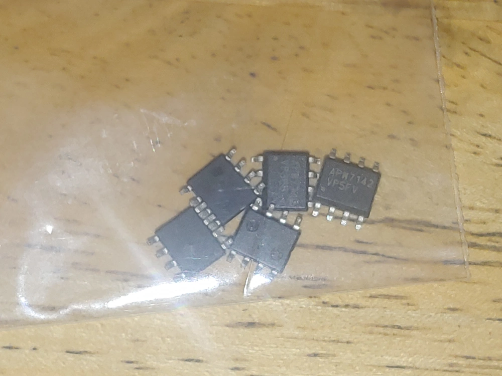
It has been just over 15 days since I ordered the replacement buck converter to replace the one that burned out on our Nvidia 980ti graphics card. I found a retailer on Ebay that sells the ANW7142 chip You can find the datasheet at the preceding link, and bought 5 of them for right around $7. It’s always a good idea to order a few spares because these things are small and can be fragile. They also don’t tend to respond well to static electricity. A little possible foreshadowing there?
The parts arrived a few days ago from China. An under 14-day turnaround isn’t too bad although I must admit I was more than a little disappointed when they showed up and inside of the padded envelope, I found them like this. Instead of an ESD bag like they belong in.
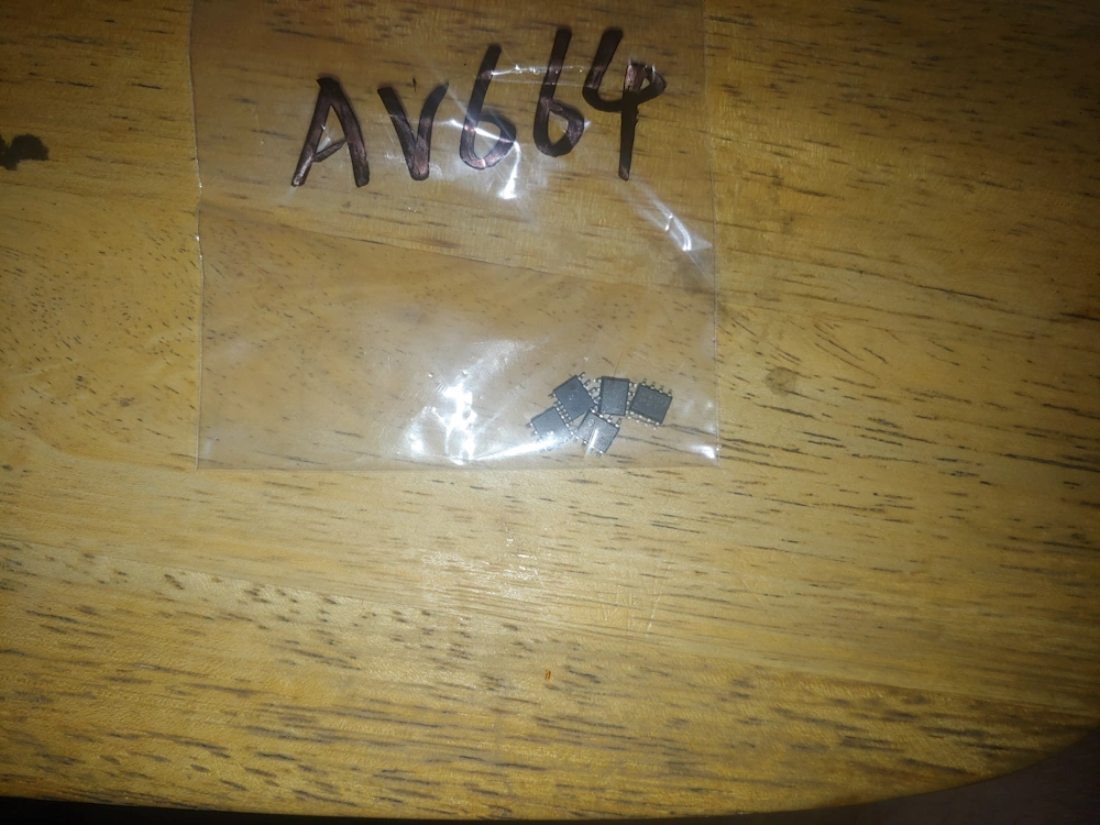
It’s never a good sign when your electronic components come in a package that looks like something you’d buy from a sketchy guy at a rave. I’m not sure if I’m supposed to solder those to a circuit board or crush them up and snort them off the back of a toilet.
Fix a Burned-Out Graphics Card: Prepping the Board
The first item of business is to remove the burned-out IC. The “proper” way to do this would be to use a hot air soldering gun, concentrate the heat on my buck converter and possibly shield any components nearby. I’ve been meaning to either buy or build a hot air soldering iron for some time now, but seeing as how I haven’t, we’ll have to use the less precise method of using a bit of flux, a regular soldering iron and some solder wick.
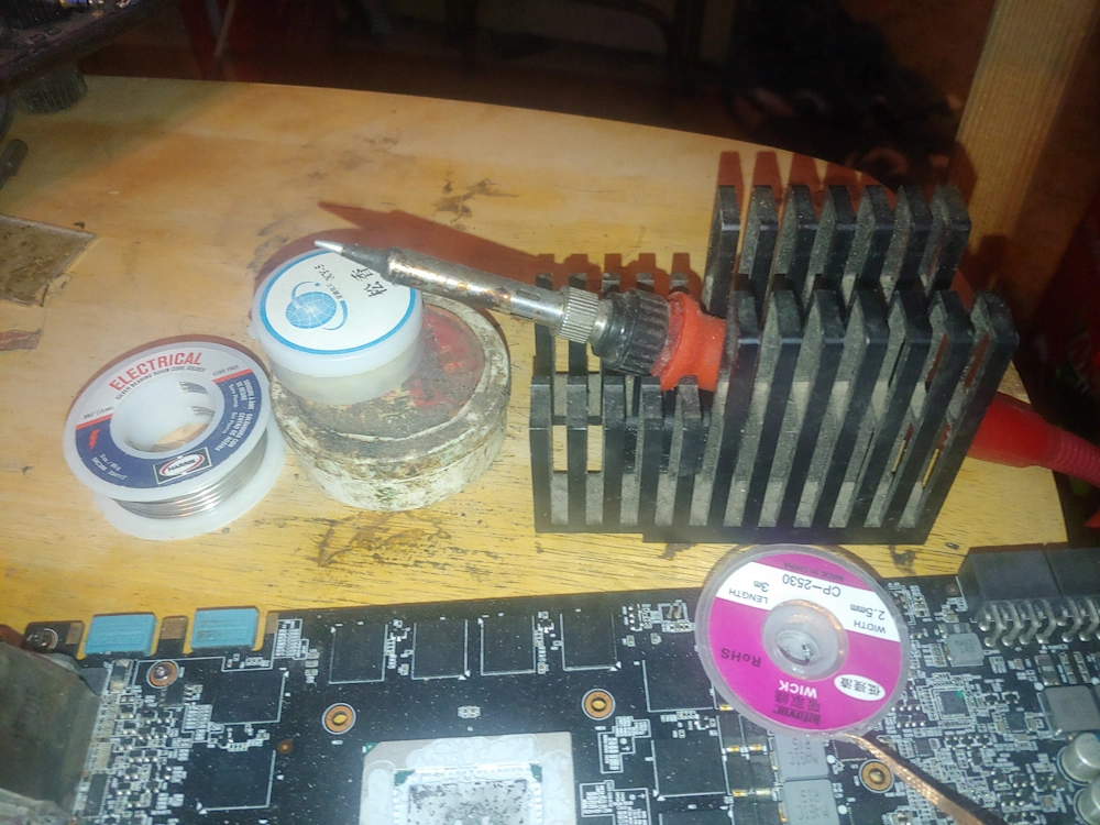
Solder wick actually works best when you use an iron for heat if the tip of the soldering is tinned with a bit of solder first. I know it feels weird to be adding solder to something your trying to desolder but trust me it works.
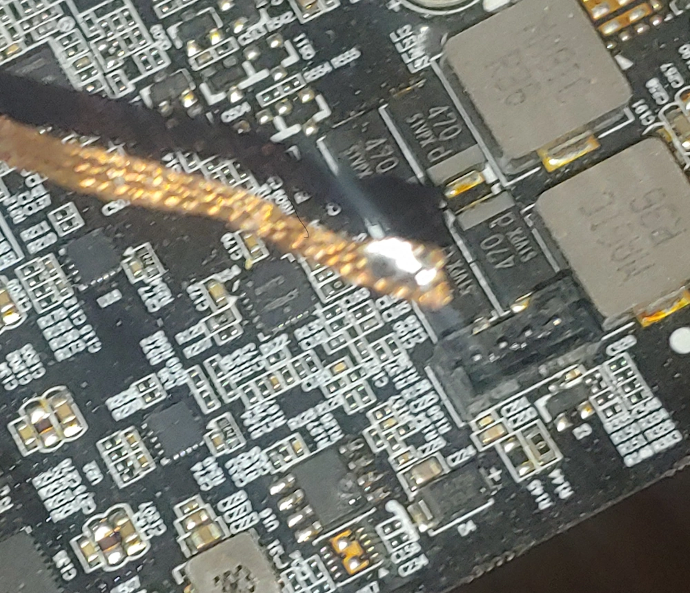
Another trick if you are forced to use solder wick with a soldering iron is to cut off a length of wick just long enough to cover the area, you’re trying to desolder. This way all of the heat from the soldering iron will be concentrated by where your work piece is at and not traveling up the length of the wick and being dissipated off into the room.
Fix a Burned-Out Graphics Card: Removing the Faulty Component
Now that you have all of your tools and supplies ready go ahead get a little flux along the length of your solder wick and press it gently over the pins on one side of the chip.
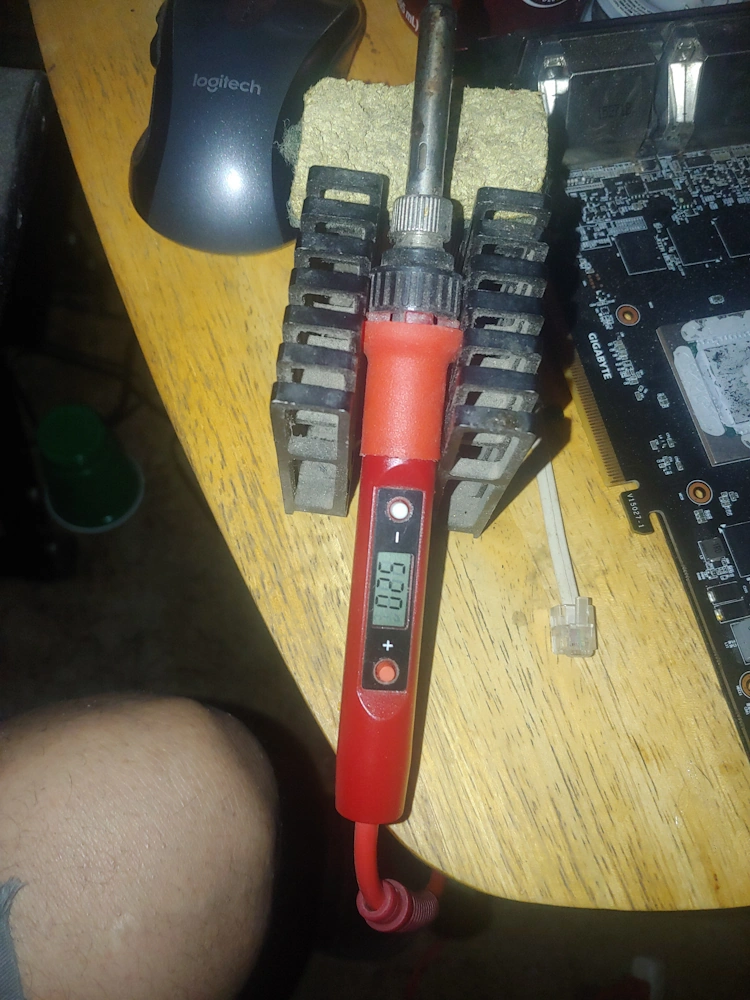
I can’t recommend highly enough that anyone who wants to successfully solder electronic components get a soldering iron where you can control the tip temperature. I use this inexpensive digital iron, I think it cost me around $20. You can also get one that has a potentiometer in the handle for about half the price, or an even cheaper option is to get a $2 60W iron from the dollar store, .17c a 1 gang electric box, a $3 dimmer switch, and a female electric plug.
In addition to being the cheapest route using the last option also gives you a variable AC power supply so you can make any cheap fixed speed tools you may have laying around the house multi-speed. I in fact used that exact setup for years till I burned my dimmer out using it with a big AC motor it had no earthly business being hooked up too.
Once you heat the wick you should be able to tell when the solder has gone molten and been absorbed by the wick. Go quickly from one pin to the next, it is helpful if you have a hobby knife or something to put under the chip and apply just a little bit of upward pressure as you desolder the first set of pins. Once you get the first side free it should look something like this.
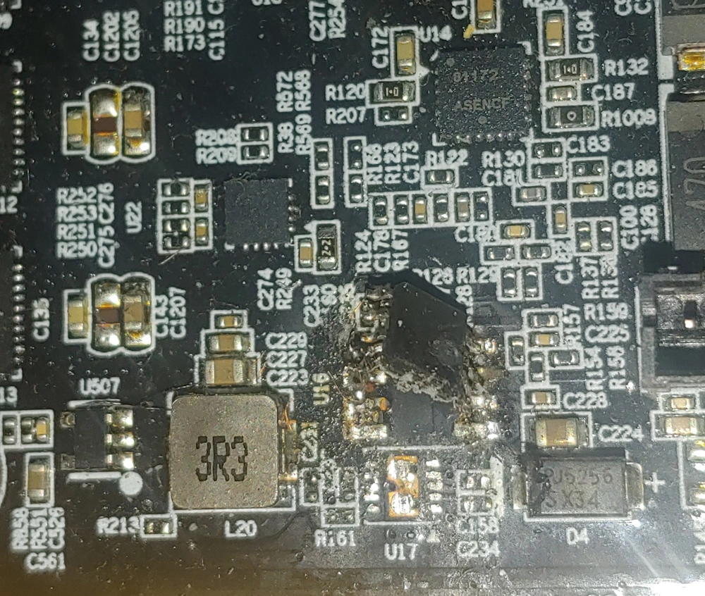
Don’t worry we’ll clean up those contacts and make sure they’re not shorted. Also be VERY CAREFUL TO ONLY DESOLDER THE BAD CHIP! If you manage to knock off any or those resistors, or capacitors next to the chip you’re going to be in some real trouble. A little bit of care can be the difference between success and failure at this juncture.
Here is a picture from the previous post in this series showing the area before we began working on it.
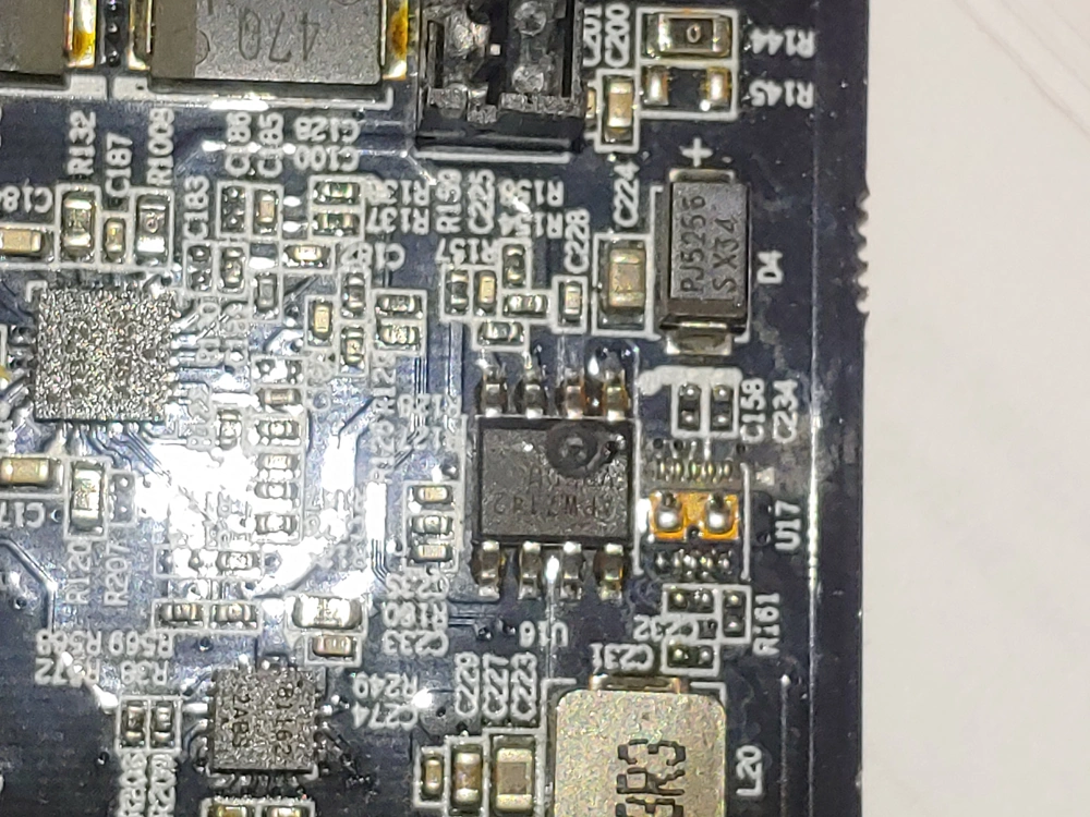
We actually got quite lucky as the area to the right of the chip in this picture is completely unpopulated so no need to be extra careful there. The only thing to be wary of is to not accidentally jumper any of those blank sets of pads. That would probably be very bad news if we were to do so.
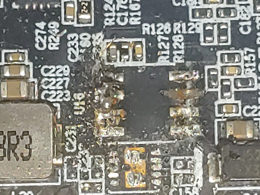
Here we have the card with the buck converter depopulated from the circuit board of the graphics card. Again, I’m using my phone to take these pictures and it does some funny things when you try to zoom in this far. The only issue we have run into thus far is that we tore the solder pad for the one of the legs on the right-hand side 2nd from the top.
A quick peruse of the datasheet shows that both of the top right legs in are labeled “dx” or modulated out-puts. They out put the voltage the buck converter is set to step down too. I plan to just solder this one to the spot where the pad was and keep my fingers crossed. If it doesn’t work the first time, I may short those two together and lay down a solder pad covering both legs.
Fix a Burned-Out Graphics Card: Prepping to Replace the Faulty Component.
On the cards side all that’s required to prepare for the replacement component to be mounted is to clean the depopulated spot. I used 97% isopropyl alcohol and a Q-Tip.
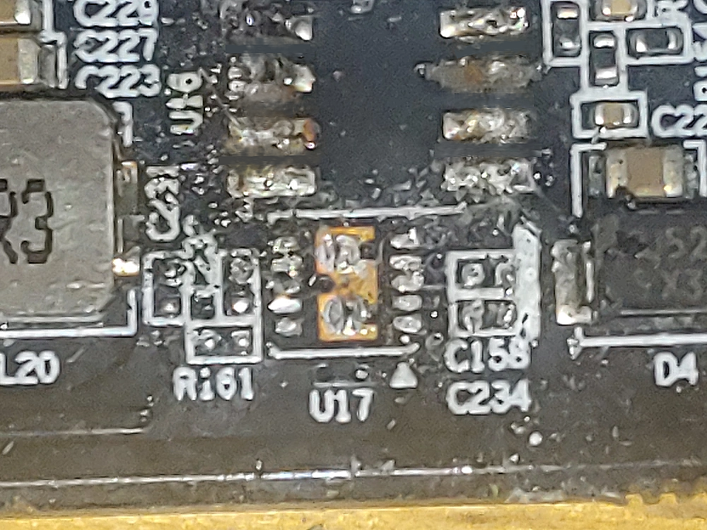
I spent a little time in photoshop to get this image to look something like it actually appears to the naked eye. All of the flux and excess solder that was left behind after the chip was removed has been cleaned away while being careful not to damage the solder pads where the new chip needs to be placed.
On the chip side I set my soldering iron to 430F or 5 degrees hotter than the temperature required to melt the solder I’m using. I then tin the soldering iron very well, grab the new chip with a pair of forceps and attempt to carefully add just a tiny bit of solder to each leg of the new chip.
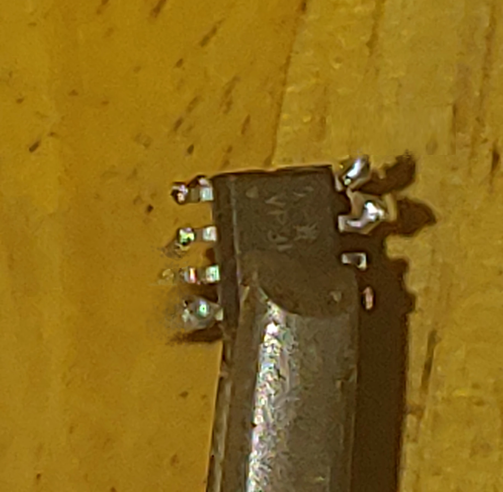
Again, that doesn’t really look much like it does in person, but you get the idea. The reason we use a very low heat setting is because all of that heat is going to go directly into the chip. This is actually my second attempt. The first one I was afraid I’d overheated and ruined the chip, so I broke out a spare.
Fix a Burned-Out Graphics Card: Attaching the New Component
After adding just, a dash of flux to each leg of the chip it was time to attach it to the graphics card. For this part I turned to heat way up on my soldering iron to 600F. The reason being that I won’t be introducing any heat until I am positive, I have everything lined up exactly as I want it, and when I add heat to it, I want to melt the solder and flux mixture instantly, fusing it to the pad and so I don’t have to spend any extra time with the iron pumping heat into both the chip and the card.
I thought about adding flux to the pads on the board side but decided against it in the end. I’ve had bad experiences with solder running and shorting things I don’t want shorted when I’ve attempted do it that way in the past. That is sure to ruin your attempt to fix a burned-out Graphics Card.
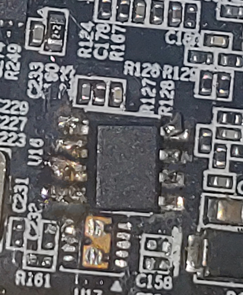
The bad buck converter has been successfully replaced on the graphics card with an identical IC. To the naked eye this repair looks about 1000x better than it does all zoomed in with my lousy LG Phone’s camera.
The only point of concern I still have is the fact that I was never able to remove the protective shield from the bottom of this graphics card. There is a greater than zero chance that there are additional component(s) underneath that have gone bad as well. I made a couple halfhearted attempts to remove the shield but the Philips screws holding it in place started to strip so I decided against getting any further along that road.
Fix a Burned-Out Graphics Card: Final Reassembly
All that is left to do is load up the contact points with a generous helping of zinc oxide thermal paste, reattach the heatsink, plug the fans back in, snug everything up firmly and then decide if I really want to stick this thing in my gaming pc?
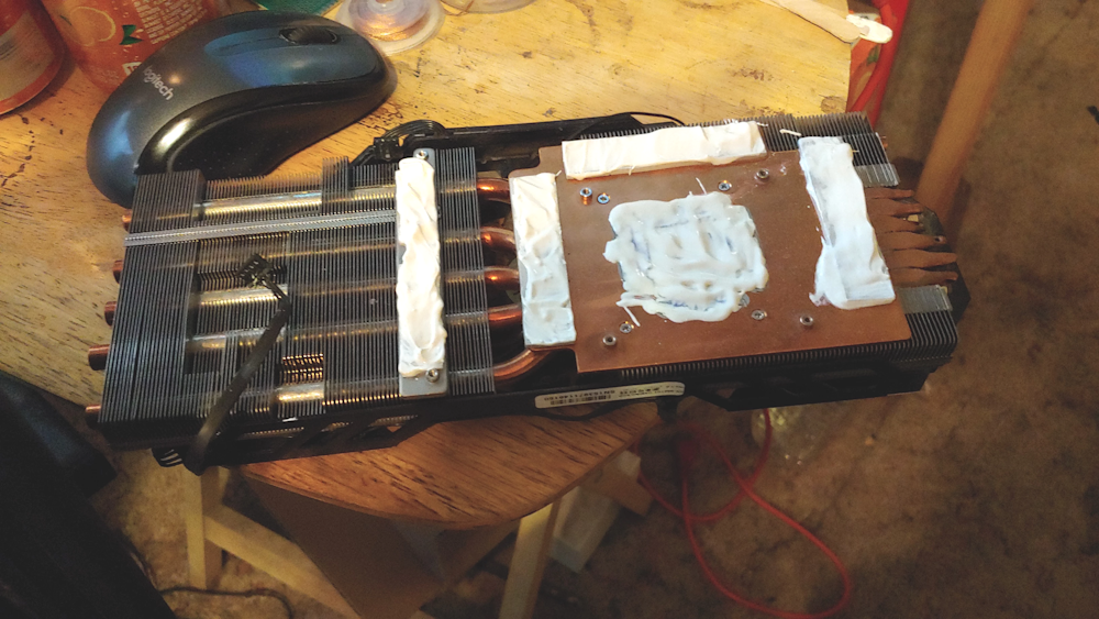
My camera takes a pretty decent picture provided it’s not zoomed in all the way on something tiny.
I put the chance of some failure harming the motherboard as extremely low but again greater than zero so in this instance discretion is the better part of valor and for the trial run, I’ll use my media center as a guinea pig. If I the worst does happen, and this thing trashed the PCIE port on the media center it’s no real loss. In fact, I’m about positive that moving transcoding off of it and onto the client devices would result in a better experience anyway.
Update
I got one of the two screws that hold the bottom shield removed! I then pulled it down and away from any components and rotated it to the side so I could verify that all of the components underneath were in fact good.
I have also received information about what the resistance is supposed to be for the memory chips as well as the power regulators that are in the same area as my burned-out component. After checking that those all fall within acceptable levels, I will be confident enough to plug this thing into my gaming PC.
Related
Don’t miss out on part number 1 of this series. How to Fix a Burned-out Graphics Card pt1.
Once you have rescued your video card it’s time to put it to some use. Check out how to Setup Triple Monitors using 3 TVs and Nvidia right here.
Still haven’t got your hardware fix? Go ahead and check out the 2-part series on setting up bass shakers with, Setup Bass Shakers for your Sim Rig pt1 and Setup Bass Shakers for your Sim Rig pt2. In part one we cover the hardware side, with part two covering the software you’ll need.
