Table of Contents
Introduction
With the ongoing chip shortage, and retailers price gouging anything with a microchip on board I figured it was time to look at a some less popular — hopefully less expensive as well — alternatives to the most popular microcontrollers, the Arduino and possibly the Raspberry Pi. This is the first in a series of posts on this topic.
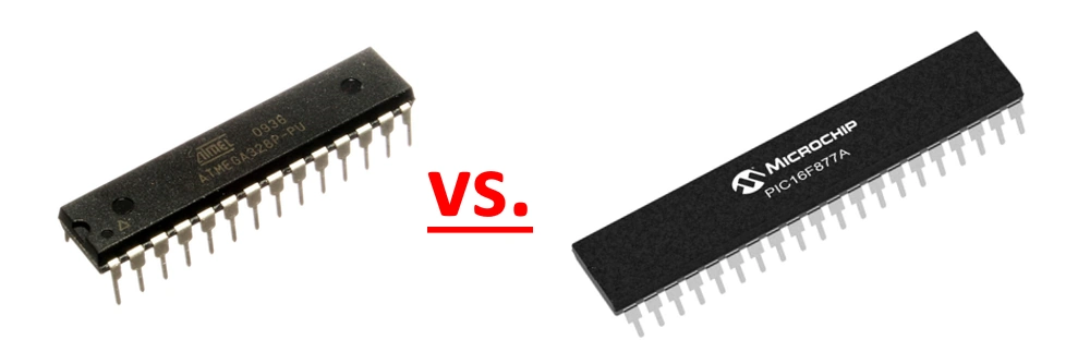
In this article, we will compare the PIC Microcontroller with the Arduino Board which is based on the Atmega328 Microcontroller — The Arduino Uno. — First we’ll go over exactly what a PIC Microcontroller is, its pinout and how that compares with the Arduino. Finally, in the end, we will compare the Arduino and PIC Microcontroller.
PIC Microcontrollers
The PIC microcontroller is really a family of microcontrollers manufactured by microchip. The name PIC is an acronym; the
- The P is for peripheral.
- The I is for the interface.
- And the C for the controller
So full meaning of the acronym PIC is “Peripheral Interface Controller.” Okay so what is a peripheral interface controller you ask? Well to give an example, say you want to turn on and off the lights and fans in your PC case using the computer keyboard buttons “A” and “B”. How to accomplish this? Well one way is to use a PIC microcontroller. The pic microcontroller connects and controls the computer and keyboard with the position between them. Before we go any further lets first see the family of PIC microcontrollers. The PIC microcontroller product family currently consists of 6 groups. The names of six groups of microcontrollers are.
- First is PIC 10FXXX this microcontroller uses an 8-bit architecture. Datasheet here.
- Second one is PIC 12CXXX & PIC 12FXXX these microcontrollers use either a 12 or 14-bit architecture.
- Third is the PIC 16C5X this microcontroller is an EPROM-ROM based 8-bit architecture. Datasheet here.
- Fourth is the PIC 16CXXX or PIC 16FXXX microcontroller of this model can take 12 or 14-bit architecture. Datasheet here.
- Fifth is the PIC 17CXXX and this microcontroller can take 16-bit architecture. Datasheet here.
- Last is the PIC 18CXXX or PIC 18FXXX and this microcontroller uses an 8-bit architecture. Datasheet here.
The XXX means you can use three numbers in the XXX space as the name of the model serial number.
Now lets look at the PIC 16FXXX microcontrollers family.
- First IC is PIC16F84 or PIC16F84A. This IC has 18 pins.
- Second is PIC16F88. This one also has 18 pins.
- Third is PIC16F72 or 16f73. This IC has 28 pins.
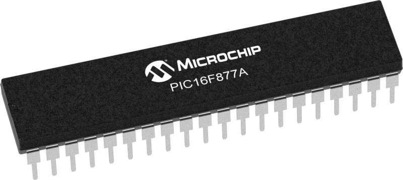
- Fourth is PIC16F877 or PIC16F877A. This IC has 40 pins.
The PIC16F877 is currently the IC with the most pins in this PIC series.
Pin Description:
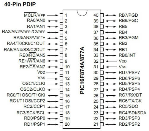
Now let’s look at the pinout of the PIC16F877A. It is a CMOS flash-based 8-bit microcontroller based on microchips PIC architecture.
There are a total of 40 pins. Port A has 6 pins, Port B, Port C, and Port D each have 8 pins, and port E has 3 pins. So, from Port A to Port E, we have a total of 33 input and output pins — IO’s —. After that, we have two VDD pins, two VSS pins, one MCLR pin. The final one MCLR is the master clear pin of the microcontroller. Then we have one pin for OCS1 and one pin for OCS2 where the OCS1 is the oscillator input and OCS2 is the Oscillator output.
The PIC microcontroller also consists of pins for serial communication RX and TX. The RX is serial input and TX is serial output. Together these two pins are used for asynchronous serial communication with serial devices. After that, we have SCL and SDA pins where the SDA is serial data and SCL is a serial clock. These two pins from the two-wire I2C –Eye-Square-Cee– integrated circuit of the PIC microcontroller.
Next we have four pins SD0, SDI, SCK, and the SS Pin. These four pins form the SPI or serial peripheral interface of the pic microcontroller. Now from AN0 to AN7, we have 10-bit ADC –analog to digital converter. — Then we have RB0 which is the external interrupt pin. CCP1 and CCP2 are the two PWM modules –Pulse Width Modulation. — PC0 to PC7 we have the parallel slave port with external read-write and CS control. The parallel slave port is 8-bit.
Arduino Microcontrollers
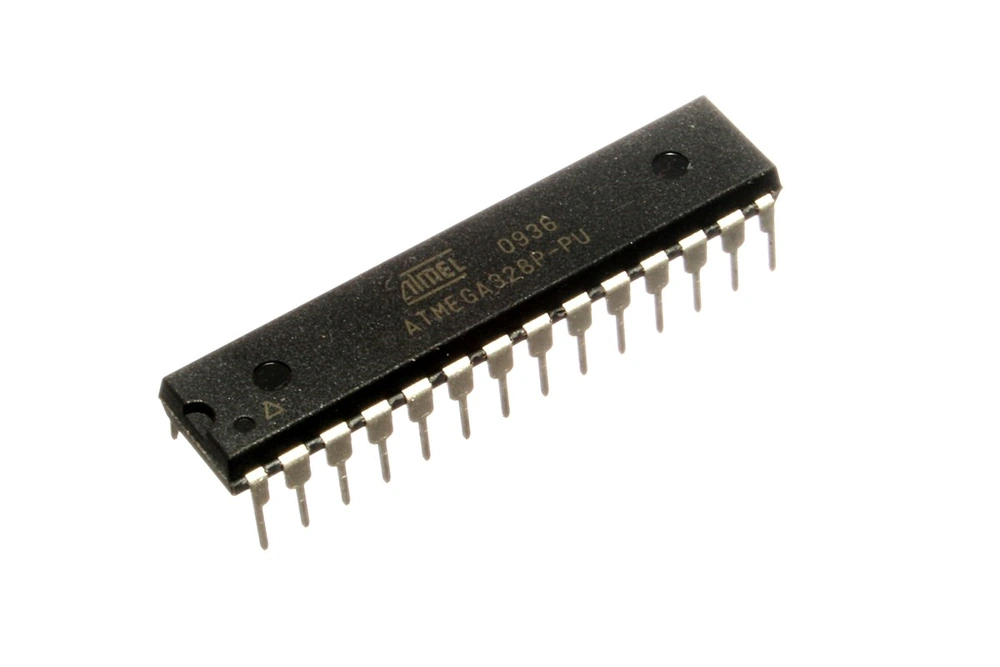
The heart of the most common Arduino family of boards — the Uno — is an atmega328 microcontroller. This microcontroller is manufactured by ATMEL Corporation. The operating voltage of the microcontroller is 5 volt it has a CPU speed of 16 megahertz. There are 6 analog inputs or output pins which you may also designate as digital IO’s in the software.
The Uno has a total of 14 digital input/output pins out of which 6 can be used for pulse width modulation — PWM. — A common use of a pulse width modulation signal is to vary the intensity or the speed at which an electric motor, or servo moves at as well as things like varying the intensity of light put out by LED’S.
There is EEPROM of 1kb SRAM of 2kb flash memory of 32kb which is where you store the program or firmware you write for the chip. UART — Universal Asynchronous Receiving Transmission — accessible either through pin headers or via USB, it has a reset pin which when pressed the microcontroller is going to cycle power then the program will reload from setup.
The pin numbers A4 and A5 which are analog pins has SDA and SCL input which can be used to receive a real-time clock configuration when used with ds1307. The digital pins 0 and 1 are used for serial communication RX pin 0 for receiving and TX on pin 1 for transmission, pins 2 and 3 which are digital can also be used as interrupts.
Atmega 328P description:
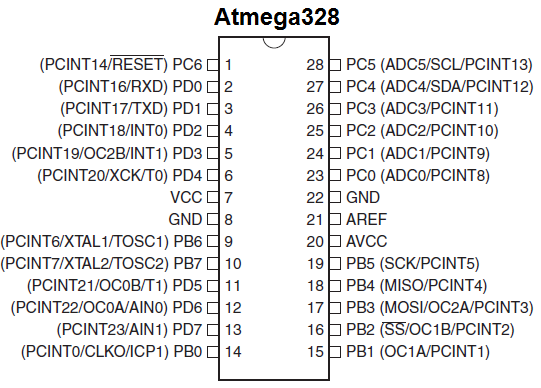
Atmega328 is low power CMOS 8-bit microcontroller based on enhanced AVR architecture. It has total number of 28 pins out of which 14 are digital output input pins from D0 to D13. It also has 6 ADC channels from A0 to A5 these form the analog to digital converter of the atmega328. It also has 6 PWM channels and two pins for XTAL1 and XTAL2.
Two pins for ground. Pin number 7 and pin number 20 are VCC. Pin 21 for analog reference. One pin for reset. So when this pin is pulled low the microcontroller will cycle power, reset and the microcontroller will be reset initializing from the setup sequence. One pin for RXD and one pin for TXD. The RXD and TXD form serial communication with the microcontroller.
The atmega328 also has some special pins like SCK which stands for serial clock, MISO stands for master input slave output, MOSI stands for master output slave input, SS stands for slave select. Together these four pins form serial peripheral interface of the atmega328. After that we have SCL and SDA which are the serial clock and serial data which form the I2C port of the atmega328.
The operating voltage of this microcontroller ranges from 1.8V to 5.5V but typically we used 5V for these purposes. It can be combined with 16MHz Crystal oscillator along with 22pF capacitor to form the crystal oscillator circuit. We 32KB of flash memory, 2KB of SRAM and about of 1KB EEROM.
PIC as an Arduino Replacement
To compare the PIC microcontroller and Arduino UNO, first of all, as stated above Arduino is not actually a microcontroller itself. It is a microcontroller board or prototyping board along with the necessary tools to program it for a vast array of different purposes. The UNO has an AVR atmega328 microcontroller at its heart.
PIC microcontrollers on the other hand are a family of microcontrollers made by microchip, they are mostly sold as plain chips and we need to wed them to a circuit board to do anything interesting. This is accomplished via a “sap socket” and a few cables, also external programmers like “Pick It 2” or “Pick 3” are needed to program the microcontroller using “MPLAB X IDE.” The software has less libraries as compared to an Arduino UNO, there are not nearly as many examples of code or tutorials to pick up some of the more esoteric aspects of this chip.
Additionally, an Arduino UNO is a far more cost-effective solution compared to PIC and it comes under open-source hardware, cross platform programming is also standard be it on Windows, Linux, or Mac. Meanwhile most of the pic microcontrollers are only programmable in Windows. The Arduino can be connected to the computer using a USB cable. Arduino has another microcontroller that acts as programmer therefore it does not require an external device for programming. The programming environment is very easy to use even for beginners the library of examples are also plentiful and accessible in the IDE. So, all you need is a USB cable Arduino software and Arduino board then you are ready to go.
The PIC microcontroller on the other hand is a programmed and developed using MPLAB X software. The MPLAB X software is a free tool much like the Arduino IDE, but you have to pick the compiler yourself. We need more tools namely a dedicated programmer for pic microcontrollers, while in Arduino we only need an Arduino board, Arduino software, and USB cable.
PIC Microcontroller Features
| Operating Frequency | 48MHz |
| Program memory | 32Kb |
| Program memory (instruction) | 16Kb |
| Data memory | 2 Kb |
| EEPROM | 256 bytes |
| Interrupt sources | 20 |
| I /O ports | Port A, B, C, D, E |
| Timers | 4 |
| PWM modules | 1 |
| Serial communication | MSSP, Enhanced USART |
| USB | 1 |
| Streaming parallel port | Yes |
| 10 Bit analog to digital module | 13 input channels |
| Comparators | 2 |
| SRAM | 14Kb |
| Clock Speed | 16MHz |
Arduino Features
| Operating Frequency | 1Khz |
| Program memory | 1Kb |
| Program memory (instruction) | 16KB |
| Data memory | 32KB |
| EEPROM | 1024 bytes |
| Interrupt sources | 25 |
| Digital I/O pins | 14 |
| Analog input pins | 6 |
| Timers | 4 |
| PWM modules | 6 |
| Serial Communication | UART, TTL, SPI |
| USB | 1 |
| Streaming parallel port | No |
| 10 Bit analog to digital module | 6 |
| Comparators | 3 |
| SRAM | 2 Kb |
| Clock Speed | 16MHz |
Architecture:
Both are 8-bit RISC platforms, so the base architecture is the same. PICs are older so they are less efficient pretty much a given with older technology and thus they cannot keep up with newer hardware in terms of cost. The AVR atmegas are newer and run faster with more features and have a support of open-source tools (like the GCC compiler) and have cheap tools like the Dragon programmer and debugger.
You may not notice any difference in the final product when you have connected relays, buttons, encoders, or LEDs. But when we try complex projects like hardware interfacing, data communication and large data processing, then the difference between the Arduino and PIC will become obvious. PICs have a lot of legacy information out there but AVRs have cheap tools that make things easier (PIC does not have a good open-source compiler.) This is why the Arduino platform is as popular and widespread as it is.
So is a PIC a viable alternative to an Arduino?
The short answer is no. Not for most people, or most applications unfortunately.
The Arduino is far superior because it is very user friendly compared to the PIC. If you want to load a program onto an Arduino, it’s just a few clicks in the Arduino IDE and done. Meanwhile PIC we will have to perform quite a few complex steps simply to upload the code in the controller and that is only for non-complex projects.
Related
You can learn all about how to program our favorite flavor of Arduino around here the Arduino Leonardo to be a game controller using the “Joystick Library” here.