Table of Contents
Introduction
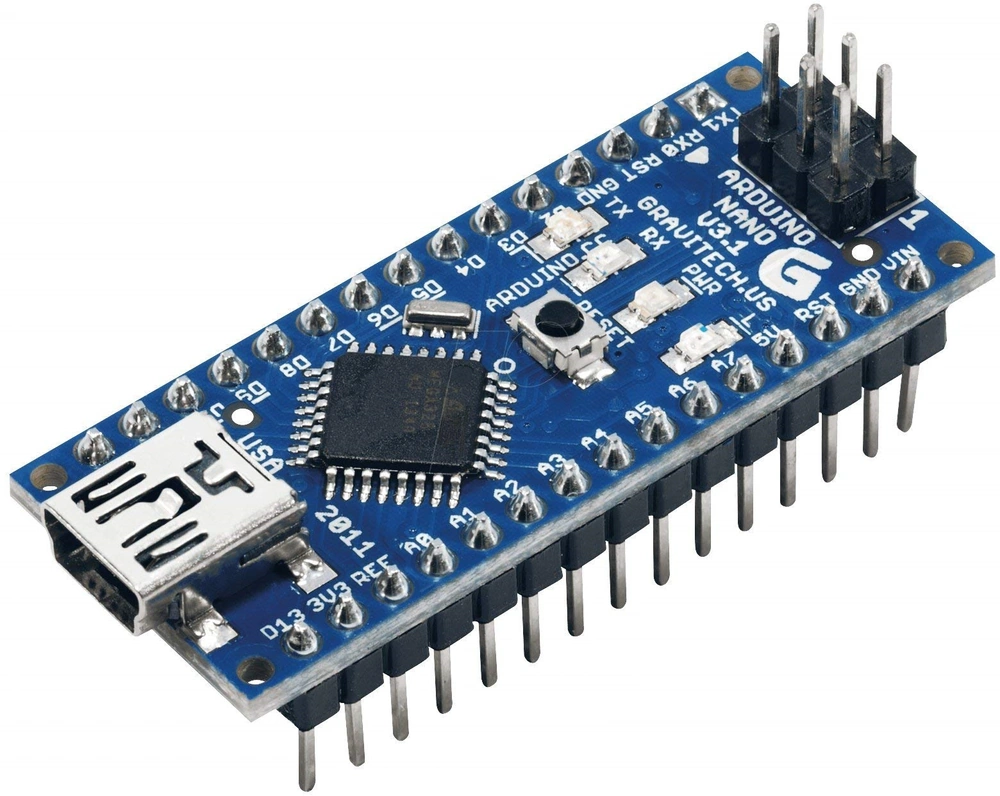
The Arduino Nano is a powerful microcontroller board known for its compact size and versatility. In this blog post, we will explore the various aspects of the Arduino Nano, including its specifications, pinout details, communication interfaces, memory, power options, compatibility, and programming capabilities. Whether you’re a beginner or an experienced maker, understanding these features will empower you to make the most of the Arduino Nano for your DIY projects.
Specifications
The Arduino Nano comes with the Atmel ATmega328P microcontroller chip, — the same chip found in the Arduino Uno — as such it offers broad compatibility with most libraries and accessories in the market for the Uno. It operates at a clock speed of 16 MHz and has 32KB of flash memory, 2KB of SRAM, and 1KB of EEPROM. These specifications provide sufficient resources for a wide range of applications.
Headers/PINOUT
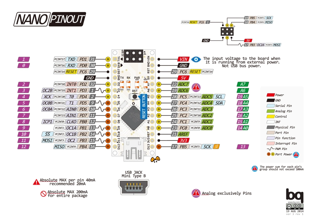
One thing to note is that this board uses the old square “Mini” USB for communication. This is an older far more robust connection than the more common “Micro” USB connector which followed. The Micro has a smaller more rounded plug which allows for faster communication but is a far more fragile physical interface. A .pdf of the entire pinout diagram can be downloaded here.
Digital I/O Pins
Each of the 14 digital pins on the Nano can be used as an input or output, using pinMode(), digitalWrite(), and digitalRead() functions. They operate at 5 volts. Each pin can provide or receive a maximum of 40 mA and has an internal pull-up resistor (disconnected by default) of 20-50 kOhms. In addition, some pins have specialized functions:
- Serial: 0 (RX) and 1 (TX). Used to receive (RX) and transmit (TX) TTL serial data. These pins are connected to the corresponding pins of the FTDI USB-to-TTL Serial chip.
- External Interrupts: 2 and 3. These pins can be configured to trigger an interrupt on a low value, a rising or falling edge, or a change in value. See the attachInterrupt() function for details.
- PWM: 3, 5, 6, 9, 10, and 11. Provide 8-bit PWM output with the analogWrite() function.
- SPI: 10 (SS), 11 (MOSI), 12 (MISO), 13 (SCK). These pins support SPI communication, which, although provided by the underlying hardware, is not currently included in the Arduino language.
- LED: 13. There is a built-in LED connected to digital pin 13. When the pin is HIGH value, the LED is on, when the pin is LOW, it’s off.
Analog Input Pins
The Nano has 8 analog inputs, each of which provide 10 bits of resolution (i.e. 1024 different values). By default, they measure from ground to 5 volts, though is it possible to change the upper end of their range using the analogReference() function.
Analog pins 6 and 7 cannot be used as digital pins.
Special Pin Functions
Some pins have specialized functionality:
- I2C: A4 (SDA) and A5 (SCL). Support I2C (TWI) communication using the Wire library (documentation on the Wiring website).
- AREF. Reference voltage for the analog inputs. Used with
analogReference(). - Reset. Bring this line LOW to reset the microcontroller. Typically used to add a reset button to shields which block the one on the board.
Communication Interfaces
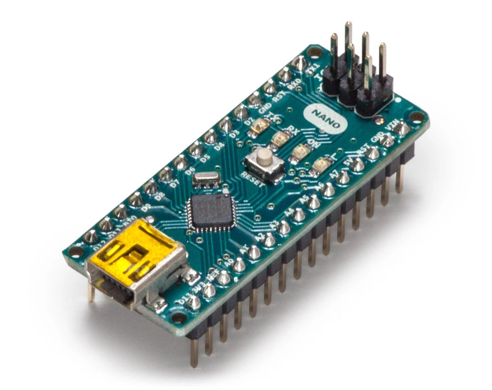
The Arduino Nano has a number of facilities for communicating with a computer, another Arduino, or other microcontrollers.
The ATmega328 provide UART TTL (5V) serial communication, which is available on digital pins 0 (RX) and 1 (TX). An FTDI FT232RL on the board channels this serial communication over USB and the FTDI drivers (included with the Arduino software) provide a virtual com port to software on the computer.
The Arduino software includes a serial monitor which allows simple textual data to be sent to and from the Arduino board. The RX and TX LEDs on the board will flash when data is being transmitted via the FTDI chip and USB connection to the computer (but not for serial communication on pins 0 and 1). A SoftwareSerial library allows for serial communication on any of the Nano’s digital pins.
The ATmega328 also support I2C (TWI) and SPI communication. The Arduino software includes a Wire library to simplify use of the I2C bus. To use the SPI communication, please see ATmega328 datasheet.
Memory
With 32KB of flash memory, the Arduino Nano provides ample space for storing your program code. The 2KB of SRAM (Static Random Access Memory) allows for efficient data storage and manipulation during runtime, while the 1KB of EEPROM (Electrically Erasable Programmable Read-Only Memory) enables non-volatile data storage.
Power
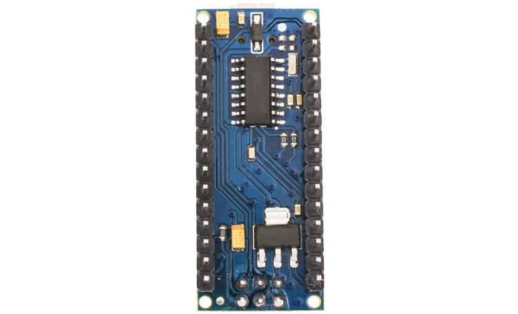
The Arduino Nano can be powered in multiple ways. It can draw power from the USB connection, making it convenient for development and testing. Alternatively, you can provide power through an external power supply connected to the VIN pin or directly to the 5V pin. The Nano includes a built-in voltage regulator, allowing it to operate with a wide range of input voltages.
Compatibility
One of the significant advantages of the Arduino Nano is its compatibility with the Arduino ecosystem. The Nano can be programmed using the Arduino IDE (Integrated Development Environment), which offers a user-friendly interface and a vast library of pre-written code. Moreover, the Nano shares the same programming language and core functionalities as other Arduino boards, making it easy to transition between different models.
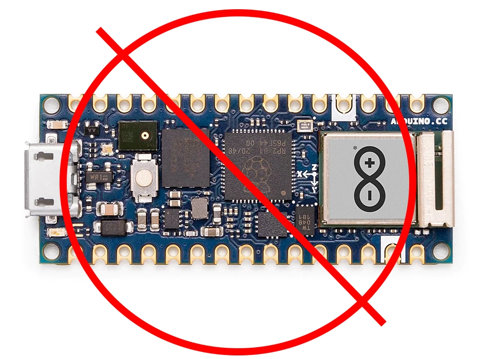
Not to be confused with the Arduino Nano RP2040!
Programming
The Arduino Nano can be programmed with the Arduino software (download). Select “Arduino Duemilanove or Nano w/ ATmega328” from the Tools > Board menu (according to the microcontroller on your board). The ATmega328 on the Arduino Nano comes preburned with a bootloader that allows you to upload new code to it without the use of an external hardware programmer. It communicates using the original STK500 protocol. You can also bypass the bootloader and program the microcontroller through the ICSP (In-Circuit Serial Programming) header using Arduino ISP or similar.
Conclusion
The Arduino Nano is a versatile microcontroller board that packs impressive specifications, extensive connectivity options, and a user-friendly programming environment. By understanding its pinout details, communication interfaces, memory, power options, compatibility, and programming capabilities, you can unlock the full potential of the Arduino Nano for your DIY projects. Whether you’re a hobbyist, student, or professional, the Arduino Nano offers endless possibilities for creativity and innovation.
Related
Need to check the specs of a specific microcontroller board? See our comparison table here for a quick reference for all of the boards we have covered so far. Here you can find all of the reviews of the microcontroller boards we covered thus far.
